Skip to content
QuinciSoft

// ESP32 · C++ firmware · Power circuits

Domotica Casa

A home automation system based on ESP32 microcontrollers, designed and built for educational purposes, for both the code and the electronics.

  • Hardware
  • Code
  • Mains voltage

Warning: mains voltage. Some nodes (nodo_fuori, nodo_boiler) drive loads connected to the 230 V mains: a mistake can cause electric shock and fire. Always work with the circuit disconnected from the mains, use an insulating enclosure and a suitable fuse, and do not touch anything while it is powered. If you have no experience with mains voltage, do not build them. The project is described for educational purposes: building it is the responsibility of whoever does it.

The project

The system is made of several nodes distributed around the house, each with a precise task (outdoor light, bathroom light, doorbell, boiler), coordinated by a central server with a web dashboard. Every choice, from the firmware to the power circuit, is documented step by step, because the value of the project lies in understanding how and why it works.

Every node and the server have a dedicated page, with the description of the project and the material to download (schematics, sources, support files): you will find them in the list The nodes.

Architecture
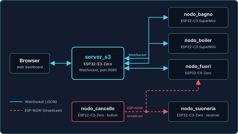
Architecture diagram: the browser shows the dashboard of server_s3; server_s3 talks over WebSocket with nodo_bagno, nodo_boiler and nodo_fuori; nodo_cancello sends an ESP-NOW broadcast message to nodo_fuori and nodo_suoneria.
Architecture of the system: server, nodes and doorbell.

The S3 server collects the telemetry and the commands of the nodes over WebSocket, a two-way connection that stays open and lets the server send data without the browser asking for it. The button of the gate node reaches nodo_fuori and nodo_suoneria with an ESP-NOW broadcast message: ESP-NOW is an Espressif protocol that lets ESP32 boards talk to each other without a router, and with the broadcast address the message reaches all the nodes that are listening.

The nodes of the system

The server and every node have their own page: open the one you are interested in to read the description and download the material. The pages of the nodes are currently in Italian only.

Hardware

The system uses ESP32 boards of different families, chosen according to the pins and functions that each node requires.

Nodes, boards and functions
NodeBoardFunction
server_s3 (page in Italian)ESP32-S3-Zero (Waveshare)WebSocket server (port 8080) and web dashboard
nodo_fuori (page in Italian)ESP32-C6-Zero (Waveshare)Outdoor light, doorbell, radar, temperature sensor
nodo_bagno (page in Italian)ESP32-C3 SuperMiniBathroom light with radar
nodo_boiler (page in Italian)ESP32-C3 SuperMiniBoiler control with temperature sensor, RTC and display
nodo_cancello (page in Italian)ESP32-C3-Zero (Waveshare)Doorbell button, transmitter
nodo_suoneria (page in Italian)ESP32-C3-Zero (Waveshare)Music module, receiver

The main components

  • HLK-LD2410C presence radar: connected over UART at 256000 baud with a binary protocol.
  • WS2812 RGB LED: status indicator, with GRB colour order.
  • 230 V power outputs: MAC97 triac with MOC3021 optocoupler on nodo_fuori (the optocoupler keeps the microcontroller separate from the mains while it drives the triac); on the boiler, zero-crossing detection with H11AA1 and a mechanical relay.
  • DS18B20 temperature sensors and DS3231 clock (RTC).
  • 433 MHz remote controls for the outdoor and doorbell nodes.

Firmware and design principles

The firmware is written in C++ with the Arduino framework and ESPAsyncWebServer; every node saves its own configuration on LittleFS (ArduinoJson v7). Development is done with the Arduino IDE, and with PlatformIO (pioarduino platform) for the C3 and C6 boards.

Some strict rules apply to all the nodes:

  1. No blocking code outside the setup() function: the node must always stay responsive.
  2. Functionality comes before the interface: the control logic never depends on the web page.
  3. AUTO and MANUAL modes: in AUTO the radar and the timer decide; when going from manual to automatic the output is brought back to a low level.
  4. Light ESP-NOW callbacks: they only set a volatile flag, without slow operations.
  5. Output safety: a maximum on-time timeout blocks the output in AUTO and requires the operator to reset it manually; on the boiler the thermal protection has two levels (WARNING and CRITICAL).

On the boiler the relay is switched in sync with the zero crossing of the mains: the H11AA1 optocoupler generates an interrupt, and if the mains voltage is absent the firmware falls back to a backup switching.

Web interface and protocol

Every node exposes a local web page with WebSocket on /wsLocal (port 80); the S3 server collects the state of all the nodes in a single dashboard. The messages are in JSON format:

Messages exchanged
DirectionExample
Node → browser (telemetry){"type":"telemetry","node":"nodo_fuori","presence":true}
Browser → node (command){"cmd":"mode","value":"AUTO"}
Doorbell event{"type":"event","node":"nodo_fuori","event":"bell"}

Future developments

  • Touch display for the boiler (migration to ESP32-C6-Zero) and for the server (Nextion NX4024T032).
  • Triac shutdown on overtemperature in the outdoor node, after collecting real data.
  • Double protection of the gate node against false pulses at power-up (software window and pulldown resistor).

Do you have questions about the project?

Write to me from the Contact page: I will reply as soon as possible.

← Back to the Home automation section