

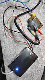
Some friends of mine who are passionate about vespa, dedicated to the modifications to the engine,
had difficulty in verifying the efficiency of the ignition coil. Using a normal tester, you can check the continuity of the circuit but not its performance.
There are many models of coils and they do not all have an electrical performance, let's say the same. So to carry out a hot test I made a small circuit,
which using the power supply of the home network, it allows me to power the coil and see how the spark is both alone and with its spark plug.
The principle is that used for dimmers, adding a snubber because our load is inductive so we need to protect our Triacs from overvoltages.
I also added a capacitor to decrease the inductive load. If you have any questions you can send them to my inbox.
Wiring diagram (download wiring diagram)
Video tester ![]()
 Top
Top
Weather station with arduino nano
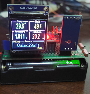
Simple weather station using a microcontroller, I chose an arduino nano, but you could also use another model, two sensors a DHT11 and a BME280,
and a 240x240Ips OLED display. I as an IDE I used visual studio code, but the code works on any IDE x Arduino.
The DHT11 sensor has 3 pins two for power supply and one for output which you can connect to the input of your choice of the microcontroller board (arduino nano),
I used pin 8. The BME280 has 4 pins two for power supply and two for I2C communication named SCL and SDA connected SDA -> A4; SCL -> A5. As the display I chose this cheap IPS 0.96 1.44 1.8 inch 7PIN 8PIN 1.3 inch SPI HD 65K Colors TFT LCD Display Module ST7789 7 pin SCL 13 RES 6 SDA 11 DC 7 Vcc +5 Gnd BLK not connected.
Library forDHT
DHT sensor library by Adafruit
BME280
Grove - Barometer Sensor BME280 by Seeed Studio (downloadSeeed)
Display
Arduino_ST7789_Fast-master (downloadFast) e RREFont-master (downloadRREFont)
Connection diagrami(downloadWire)
Source code (downloadSource)
In my code I also left a section that can be used for an ss1306 display. To understand better, I suggest you take a look at the description and example
files of the various used libraries. If you have any questions or anything else please contact me.
Top
Problems uploading sketch on esp32,lolyn,nodemcu
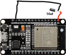
It may happen that when you upload one of our sketches on a board such as esp32, Lolyn, nodeMcu, you get this error during the upload phase
Serial port COM5 Connecting........_____....._____....._____....._____....._____....._____.....____
An error occurred while uploading the sketch _ A fatal error occurred: Failed to connect to ESP32: Timed out waiting for packet head......
The problem can be solved by inserting a 10uf electrolytic capacitor between the EN pin and the negative (GND). With the positive of the capacitor on the EN pin
Top
Configuration :
platform = atmelsamLibrary :
Adafruit ST7735 and ST7789 Library@^1.8.0PinS :
pin 3 LED_ROSSODisplay :
TFT 240x240 IPS
pin 10 TFT_CS
pin 0 TFT_RST
pin 1 TFT_DC
pin 4 SDA
pin 5 SCL
niente BLK
Enter AntiSpam code 8296 to download
Top
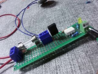
For those who usually use boards with Arduino type microcontrollers, there is the problem of managing loads
with
voltages and currents that the board's outputs cannot handle. So I thought about this little circuit,
which allows with input voltages from 2 to 5 volts in continuous, to manage loads up to 4A with voltages in alternating from 12 to 300V.
These limits can be overcome by using a more powerful triac than the one I used a bt134.
You can input both ON/OFF signals, PWM and waveforms.
If you want to handle higher loads you can replace the bt134 with a btb16.
To make it more performing replace the moc3021 with moc3061 which has zero crossing.
Any questions ? you can send them to my mailbox.
Wiring diagram (downloadWiring diagram Digital relay)
Video relay ![]()
Top